This tutorial explains how to make your own power supply unit for all your electronics and embedded system experiments. It also has a backup battery which will be used in case of power cuts and a display.
Components Required
1. SLA 12V battery
2. Banana Jack connectors female (2 pairs each)
3. Screw Terminals (1 pair)
4. SPST switch (ratings 5A or more)
5. Adjustable Voltage Regulator LM317 x 2
6. Voltage regulators 7805, 7809, 7812
7. GPCBs
8. Step-down Transformer 16-18V/3 Amps
9. 1N4007 Diodes x 4
10.Two Relay Module
11. Capacitors
12. Resistors
13. ATmega16/8 Development board
14. 16x2 LCD
15. Heat Sinks
16. Enclosure
Features:
- Inputs: 220-240V, 50Hz AC
- Outputs: 1 X 5V and 1 X 9V (available through banana jack)
1 X Adjustable voltage (available through screw terminal)
- Adjustable Voltage Range:1.25-14.5V in Mains Mode and 1.25-10.5V in Battery Mode
- Modes: 1) Battery Mode and 2) Normal Mode (Through Mains)
- Automatic Switching and Shutdown by Microcontroller
- LCD with various indicators.
Block Diagram

Fig. 1: Block Diagram of Un-interruptible Bench Top DC Power Supply
Blue lines indicate signal lines and black lines indicate power lines.
Let me explain what each block consists of and its function.
Mains Block: This consists of the transformer, bridge rectifier (4 diodes) circuit and a capacitor. This block takes in the power from a wall socket which provides 220-230V AC. The step-down transformer scales down the amplitude of the sine wave, followed by the bridge rectifier which converts it into pulsating DC which when passing through capacitor yields an unregulated DC power of 16-18V (voltage depends on transformer)

Fig. 2: Circuit Diagram of AC Rectifier used as first stage of Un-interruptible Bench Top DC Power Supply
Charger Circuit: This block mainly consists of an adjustable voltage regulator LM317 which along with other components works as constant voltage, current limited charger for our battery. Once the battery is fully charged, the circuit automatically supplies low current to the battery and goes into trickle charging mode.
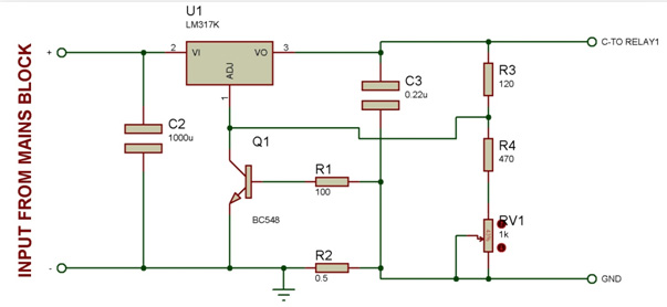
Fig. 3: Circuit Diagram of Charger used as second stage of Un-interruptible Bench Top DC Power Supply
Charge Indicator: This is nothing but two resistors arranged in the form of a voltage divider circuit. It scales down the voltage level of battery for the microcontroller to read it.
Relay 1: This is a relay module which switches between the charge indicator circuit and charger circuit depending on the command from microcontroller.
The battery’s +ve terminal is connected to the common pin. The charging circuit is connected to the Normally Open pin and charge indicating circuit is connected to the Normally Closed pin.
When the mains supply is in OFF state, the relay disconnects the charger from battery and connects it to the indicator so that the microcontroller can read the battery level and display on the LCD. When the supply is ON, the indicator circuit is disconnected and the charging circuit is connected to the battery.
Relay 2: This relay module switches between mains supply and battery supply depending on the command from microcontroller.
The battery’s +ve terminal is connected to the Normally OPEN pin while the +ve line from main power supply block is connected to the Normally CLOSE pin. The common pin of relay is connected to the DC PSU block.
When the mains are unavailable, the controller automatically switches the relay to battery mode.

Fig. 4: Circuit Diagram of Charge Indicator used as third stage of Un-interruptible Bench Top DC Power Supply
Note: The +12V for powering the relay is given directly from the battery. This allows the relay to function purely based on the command from microcontroller instead of availability of power.
Exclusive Digi-key Tools
DC PSU: This block consists of the voltage regulators and a bunch of capacitors. +5V, +9V and adjustable voltage levels are provided by the ICs 7805, 7809 and LM317 respectively.

Fig. 5: Circuit Diagram of Voltage Regulators used as final stage of Un-interruptible Bench Top DC Power Supply
Panel Display: This is the front and outer panel block which consists of the main switch, LCD displaying the voltage level, Potentiometer Knob to adjust the voltage, Banana connectors and screw terminals.
This is how I want it to look like:

Fig. 6: Image representing Panel Display of Un-interruptible Bench Top DC Power Supply
The icons on the LCD indicate the following:

Fig. 7: Image showing Icons used on display panel to show different battery statuses
Code Explanation
. Here our development board does the following tasks:
- Calculate voltage levels at variable voltage terminal and battery level using ADC
- Detecting the presence/absence of mains
- Switching supplies and charge indicator/charger by controlling relays at appropriate events.
- Displaying all the above parameters on LCD
So our code algorithm goes like this:
-Initializing the I/O ports, ADC registers and LCD functions.
- Enter infinite loop
- Check the availability of mains supply using ADC pin
- if mains available, display corresponding icons on screen
- if mains unavailable, switch to battery mode and switch ON charge indicator
- Check battery level using ADC pin
- If battery level is either of >50%, <50%, <10%, then display corresponding icons on LCD.
- If battery level close to 0%, initiate automatic shutdown sequence count.

Fig. 8: Image representing pin diagram of character LCD
Since in the last step, the mains is unavailable anyways, the power to micro-controller board, LCD and the DC PSU gets cut off and hence the unit cannot be turned ON again without providing it the supply from mains.
In case the mains become available during the shutdown process, the data on LCD goes garbage and hence we use a watchdog timer to reset the controller at the end.
The +5V line is also connected to the microcontroller board and LCD.
Circuit:

Code:


Không có nhận xét nào:
Đăng nhận xét