In many application of controlling robotic gadget it becomes quite hard and complicated when there comes the part of controlling it with remote or many different switches.
Mostly in military application, industrial robotics, construction vehicles in civil side, medical application for surgery. In this field it is quite complicated to control the robot or particular machine with remote or switches, sometime the operator may get confused in the switches and button itself, so a new concept is introduced to control the machine with the movement of hand which will simultaneously control the movement of robot.

Fig a : Robot
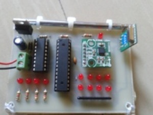
Fig b : Hand gesture sensor (transmitter)

Fig c : Hand mount
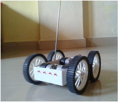
Fig d : Chassey photo (Front view)

Fig d : Chassey photo (Top view open)
Description
A Gesture Controlled robot is a kind of robot which can be controlled by your hand gestures not by old buttons.You just need to wear a small transmitting device in your hand which included an acceleration meter.This will transmit an appropriate command to the robot so that it can do whatever we want. The transmitting device included a ADC for analog to digital conversion and an encoder IC(HT12E) which is use to encode the four bit data and then it will transmit by an RF Transmitter module.
At the receiving end an RF Receiver module receive's the encoded data and decode it by and decoder IC(HT12D). This data is then processed by a microcontroller and finally our motor driver to control the motor's. Now its time to break the task in different module's to make the task easy and simple any project become easy or error free if it is done in different modules. As our project is already divided into two different part transmitter and receiver. We will discuss both of them one by one.
Accelerometer
An Accelerometer is a kind of sensor which gives an analog data while moving in X,Y,Z direction or may be X,Y direction only depend's on the type of the sensor.

Here is a small image of an Accelerometer shown. We can see in the image that their are some arrow showing if we tilt these sensor's in that direction then the data at that corresponding pin will change in the analog form.
The Accelerometer having 6 pin-
1- VDD- We will give the +5volt to this pin
2- GND- We simply connect this pin to the ground for biasing.
3- X- On this pin we will receive the analog data for x direction movement.
4- Y- On this pin we will receive the analog data for y direction movement.
5- Z- On this pin we will receive the analog data for z direction movement.
6- ST- this pin is use to set the sensitivity of the accelerometer 1.5g/2g/3g/4g.
Block Diagrams & PCB Design
Transmitter Block diagram

Receiver Block Diagram

PCB DESIGN

Components and costing
Sr.no
|
Components
|
Qty
|
Cost in Rs (INR)
|
1
|
433 Mhz RF Module
|
1
|
260
|
2
|
Ht12e
|
1
|
45
|
3
|
Ht12d
|
1
|
45
|
4
|
L293D
|
2
|
90
|
5
|
AT89S52
|
1
|
45
|
6
|
7805
|
2
|
30
|
7
|
CAPACITOR 10 UF 63V
|
2
|
2
|
8
|
11.0592 Mhz crystal
|
1
|
10
|
9
|
PBT Connector
|
6
|
24
|
10
|
PCB Manufacturing cost
|
2
|
300
|
11
|
Single pole antenna
|
2
|
36
|
12
|
Resistor 1k
|
15
|
7
|
13
|
LED 3mm
|
20
|
20
|
14
|
Atmega 8
|
1
|
75
|
15
|
Accelerometer ADXL335
|
1
|
550
|
16
|
Battery 12 v 3.5Ampere
|
1
|
350
|
Above are the standard price
Note : The costing may vary according to region / area
Application
1. Military application to control robotics
2. Medical application for surgery purpose.
3. Construction application.
4. Industrial application for trolly control, lift control, etc.
Circuit:


Code:
#include <mega8.h>
#include <delay.h>
#define ADC_VREF_TYPE 0xE0 // Read the 8 most significant bits
                          // of the AD conversion result
unsigned char read_adc(unsigned char adc_input)
{
ADMUX=adc_input | (ADC_VREF_TYPE & 0xff);
// Delay needed for the stabilization of the ADC input voltage
delay_us(10);
            // Start the AD conversion
ADCSRA|=0x40;
// Wait for the AD conversion to complete
while ((ADCSRA & 0x10)==0);
ADCSRA|=0x10;
return ADCH;
}
void main(void)
{
unsigned int x,y,z;
PORTB=0x00;
DDRB=0xFF;
PORTC=0x00;
DDRC=0x00;
PORTD=0x00;
DDRD=0xFF;
TCCR0=0x00;
TCNT0=0x00;
TCCR1A=0x00;
TCCR1B=0x00;
TCNT1H=0x00;
TCNT1L=0x00;
ICR1H=0x00;
ICR1L=0x00;
OCR1AH=0x00;
OCR1AL=0x00;
OCR1BH=0x00;
OCR1BL=0x00;
ASSR=0x00;
TCCR2=0x00;
TCNT2=0x00;
OCR2=0x00;f
MCUCR=0x00;
TIMSK=0x00;
UCSRB=0x00;
ACSR=0x80;
SFIOR=0x00;
ADMUX=ADC_VREF_TYPE & 0xff;
ADCSRA=0x83;
SPCR=0x00;
TWCR=0x00;
while (1)
      {
      // Place your code here
      x=read_adc(3);
      y=read_adc(4);
      z=read_adc(5);
        PORTB=x;
//---------------------------------------------------------------// X AXIS
//---------------------------------------------------------------     if(x>0xab)
      {
      PORTD=0x0c;
      }
            else if(x<0x9b)
      {
      PORTD=0x03;
      }
//-------------------------------------------------------------- // Y AXIS
//------------------------------------------------------------------
    else if(y>0xab)
      {
      PORTD=0x08;
      }
            else if(y<0x9b)
      {
      PORTD=0x0e;
      }
//--------------------------------------------------------------
//---------------------------------------------------------------

       else
      PORTD=0xff;
      }
}


//Receiver main program
#include<reg51.h>
void main()
{
P2=0xff;
P1=0x00;
while(1)
{
if(P2==0x80)
{
P1=0xaa;
}
else if(P2==0xe0)
{
P1=0x55;
}
else if(P2==0x30)
{
P1=0xa5;
}
else if(P2==0xC0)
{
P1=0x5a;
}
else
P1=0x00;
}
}
[/restrict]


Không có nhận xét nào:
Đăng nhận xét