Saving electricity is a major concern for domestic and industrial units. We always try hard to save electricity in many ways to reduce our electricity bills, but due to some unknown and unforeseen circumstances our efforts do not normally transform in saving electricity. Adding to our woes, we may at times forget to switch off electrical gadgets when we are not using them, especially the AC’s. This not only results in mounting electricity bills, but we also forget the fact that a resource of National Importance is being wasted. To overcome the above shortcomings, a prototype model is created which doesn’t hurt our pockets too. The name of the project is “Coin Operated Timer Control Power Supply Box to Control AC Appliances”.

Fig. 1: Prototype of Coin Operated Prepaid Power Supply System
Prototype View of Coin Operated Timer Control Power Supply Project
Block Diagram

Fig. 2: Block Diagram of AVR ATMega16 based Coin operated Prepaid Power Supply System
Block Diagram Description
Let’s discuss the components shown in the block diagram
1) AtMega 16
2) 16X2 Character LCD Display
3) Power Supply
Power supply for the complete unit can be derived from the mains using a step-down transformer of 230V AC primary to 0-12V, 500mA secondary. A full- wave rectifier followed by a capacitor filter is the output voltage and feeds it to the 5-volt regulator (LM7805) whose output is used for the power supply requirements of microcontroller circuit, other IC’s.
Fig. 3: Circuit Diagram of AC to DC Power Supply Unit

Fig. 4: Prototype of AC to DC Power Supply
4) Relay
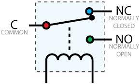
Fig. 5: Circuit Diagram of SPDT Relay
A relay is an electro-mechanical switch that opens and closes under the control of another electric circuit. When current flows through the coil of the relay, a magnetic field is created which causes the armature to move, either making or breaking an electrical connection. When current is removed from the relay coil, the armature returns to its rest position. It is important to place a diode across the coil of the relay because a spike of voltage is generated when the current is removed from the coil due to the collapse of the magnetic field. This voltage spike can damage the sensitive electronic components controlling the circuit.
(NOTE*: For more details, please refer tutorials on web or Engineer’s Garage website)

Fig. 6: Circuit Diagram of Transistor based Relay Driver
(*NOTE:In this project, I am using 12V DC relay)
5) IR Sensor
IR sensor is widely used for object detection in many applications. Here I have also used this as an obstacle which means a coin detector. The out of IR Sensor is analog by nature which is later converted into digital values using in-built ADC of the Microcontroller. IR sensor is made from one IR LED, one Photodiode and a pair of resistor. It is used to detect the presence of the coin. IR LED and Photodiode are in front of each other in a line with some distance for passing the coin. When there is no coin, IR LED constantly radiates IR Light which falls on Photodiode so that Photodiode output is low.
When a coin passes through a gap between them, it cuts the IR light so at that time output goes high. It means, whenever output goes high, a coin is passed through the gap to detect coin in this manner.
Fig. 7: Circuit Diagram of IR Sensor Module
(NOTE*: For more details, please refer to the tutorials on web or Engineer’s Garage website)
Working Principle
Circuit Diagram
For circuit diagram please click on crcuit diagram tab
Working Principle
To start the project at first we need to power-up the prototype. The power indicator LED’s (e.g. Red on power supply board and Green on MCU board) glows to show that the power supply is proper to operate. If not, please check the power supply circuit.
As soon as the power is on, the LCD shows a welcome message as given in the image below:
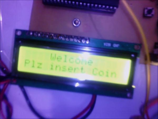
Fig. 8: Image showing display panel of coin operated Prepaid DC Power Supply
At this point the system waits for the coin to be inserted. So I made a coin box with white color shown under “Prototype View” in the image depicted above. Inside that coin box I have placed an IR Sensor, so when a coin is put inside the box, the coin passes through the gap between IR Sensor. When the coin cuts the IR rays generated by IR LED, the analog output goes high. This output connected to the in-built ADC of microcontroller converts that analog output to digital values.
So here we are making a threshold value in my C source code, e.g. 200 in my code. But before this let me tell you how to make your threshold value. Before making a thresh hold value, I did a small practical on my main board. I printed IR Sensor value on the LCD Display without coin and with coin sliding into the coin box and made a note of both the values. The Value without coin is around 900 and the value with the coin is around 90 (after ADC by MCU). So this small trick helped me to arrive at the threshold value of 200. Coming back to the project when I put the coin in the box, my threshold value, condition meets up the required value and then later I pre-increment my integer variable. In this way every time when I put a coin the system detects it and pre- increments the integer value which helps me to read as to how many coins I have inserted in the box which is also displayed on the LCD.

Fig. 9: Image showing display panel in action on Prepaid Dc Power Supply System
In this project I have followed the principle (formula) 1 coin= 1 minute of electricity, so if N numbers of coins are inserted then you shall get N Minutes of electricity. Now, since I am done with my coin insertion, I want to switch on the load for the desired no. of minutes. To do so, I have used a switch (S1) which is connected to pin PB1of the MCU and a relay with a transistor (BC547) to provide sufficient current to relay and drive. The relay and transistor’s base is connected to pin PD0.
Now when I press the switch (S1), an in-built 8 bit time of MCU gets started and goeswhich is shown in the image below on the LCD Display and runs exact numbers of minutes equal to the number of coins inserted. Parallely it makes the PD1 pin high (e.g. ‘logical 1’) thereby activating the transistor which in turn activates the relay and my AC load gets on. The timer is also shown on the LCD display in running mode, in the image below.

Fig. 10: Image showing duration of power supply charged by coins on Prepaid DC Power Supply System
Once the time completes exact numbers of minutes equal to the number of coins inserted, it makes PD1 pin low (e.g. ‘logical 0’) which turns off the transistor. In turn the transistor switches off the relay and the AC load gets switched off. The LCD Display starts to show the welcome message again.
(*NOTE: If you are not aware of TIMER Functions, please go through its tutorials which are easily available on web or visit a technical tutorial website.)
This marks the completion of the project, where the desired end result is successful. For your benefit I have a video of the working and another clip of the Proteus Simulation for better understanding of the project.
.Exclusive Digi-key Tools
Circuit:

Code:
#include<avr/io.h>
#include<util/delay.h>
#include "lcd_lib.h"
#include "adc_lib.h"
#include <stdio.h>
#include<avr/interrupt.h>
#include<timer0.h>
char A[20]="" ,ms=0,sec=0,min=0,hr=0;
unsigned int i,j,k;
unsigned char B[16];
unsigned char C[16];
main (void)
{
  ADCinit();
  LCDinit();
  LCDclr();
  LCDcursorOFF();
  DDRB=0xf0;
  DDRD=0xff;


while(1)
{
PORTB=0x0f;
i=read_adc(0);
i=i/2;

if(i>200)
{
  k++;
  LCDclr();
  LCDGotoXY(0,1);
   sprintf(C,"No of Coins=  %d",k);
   LCDstring(C,strlen(C));
   _delay_ms(1000);
}

else if(bit_is_clear(PINB,PB1))
{
  set_timer0_normal();
  set_timer0value(0);
  set_timer0_prescalar(5);
  enable_timer0_overflowint();
  sei();// enable interrupts
  PORTD=1;
}

else if(min==k)
{
  stop_timer0();
  PORTD=0;
  LCDclr();
  LCDGotoXY(0,0);
  LCDstring("    Welcome    ",15);
  LCDGotoXY(0,1);
  LCDstring("Plz insert Coin",15);
  _delay_ms(1000);
}

}}

ISR(TIMER0_OVF_vect){
set_timer0value(10);
ms++;
if(ms>10){
  ms=0;sec++;
  if(sec>59){
   sec=0;min++;
   if(min>59){
    min=0;hr++;
    if(hr>23){
     hr=0;
    }
  }
}
sprintf(A," <<<%d:%d:%d>>> ",hr,min,sec);
LCDGotoXY(0,0);
LCDdisplay(A);
}
}


Không có nhận xét nào:
Đăng nhận xét