Developed By:
Akshay Daga
Communication between two entities is important for the information flow to take place. In general the information transport system can be parallel in which the complete byte of data is sent at a time, with each bit having a separate dedicated line or it can be serial where only one communication line is available which is shared by all the bits sequentially. The pros and cons of these two systems are equivalent and selection between the two depends on the application.
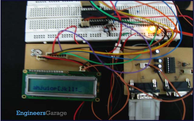
Data can be exchanged using parallel or serial techniques. Setup for parallel data transfer is not cost effective but is a very fast method of communication. Serial communication is cost effective because it requires only a single line of connection but on the other hand is a slow process in comparison to parallel communication. This article explains serial communication of AVR microcontroller (ATmega16) with PC. The data is transmitted from the controller using RS232 standard and displayed on the PC using Hyper Terminal.

There are two methods for serial data communication (i) Synchronous and (ii) Asynchronous communication. In Synchronous communication method complete block (characters) is sent at a time. It doesn’t require any additional bits (start, stop or parity) to be added for the synchronization of frame. The devices are synchronized by clock. And in asynchronous communication data transmission is done byte by byte i.e., one byte at a time. The additional bits are added to complete a frame.
In synchronous communication the frame consists of data bits while in asynchronous communication the total number of bits in a frame may be more than the data bits.
Fig. 2: Basic Frame Structure of USART in ATmega16 AVR microcontroller
There are three ways in which serial communication can be done
i. Simplex: Transmission is done in one direction.

Fig. 3: Block Diagram of Simplex Transmission in Serial Communication
ii. Half duplex: Transmission can be done in both the direction but one side at a time.

Fig. 4: Block Diagram of Half Duplex Transmission in Serial Communication
iii. Full duplex: Transmission can be done in both the direction simultaneously.

Fig. 5: Bloack Diagram of Full Duplex Transmission in Serial Communication
Atmega16 is equipped with three different kinds of serial communication peripheral systems:
i. Serial USART
ii. SPI (Serial Peripheral Interface)
iii. TWI (Two wire Interface)
SERIAL USART (universal synchronous asynchronous receiver and transmission/ transmitter):
Serial USART provides full-duplex communication between the transmitter and receiver. Atmega16 is equipped with independent hardware for serial USART communication. Pin-14 (RXD) and Pin-15 (TXD) provide receive and transmit interface to the microcontroller.
Fig. 6: Pin Configuration of USART in ATmega16 AVR microcontroller
Atmega16 USART provides asynchronous mode of communication and do not have a dedicated clock line between the transmitting and receiving end. The synchronization is achieved by properly setting the baud rate, start and stop bits in a transmission sequence.
Start bit and stop bit: These bits are use to synchronize the data frame. Start bit is one single low bit and is always given at the starting of the frame, indicating the next bits are data bits. Stop bit can be one or two high bits at the end of frame, indicating the completion of frame.

Fig. 7: Asynchronous Frame Structure in Serial Communication
Baud Rate: In simple words baud rate is the rate at which serial data is being transferred.
Atmega16 USART has following features:
· Different Baud Rates.
· Variable data size with options ranging from 5bits to 9bits.
· One or two stop bits.
· Hardware generated parity check.
· USART can be configured to operate in synchronous mode.
· Three separate interrupts for RX Complete, TX complete and TX data register empty.
USART Registers
To use the USART of Atmega16, certain registers need to be configured.
UCSR: USART control and status register. It’s is basically divided into three parts UCSRA, UCSRB and UCSRC. These registers are basically used to configure the USART.
UBRR: USART Baud Rate Registers. Basically use to set the baud rate of USART
UDR: USART data register
i. UCSRA: (USART Control and Status Register A)
Fig. 8: Bit Configuration of USART control and status register A in ATmega16 AVR microcontroller
RXC (USART Receive Complete): RXC flag is set to 1 if unread data exists in receive buffer, and set to 0 if receive buffer is empty.
TXC (USART Transmit complete): TXC flag is set to 1 when data is completely transmitted to Transmit shift register and no data is present in the buffer register UDR.
UDRE (USART Data Register Empty): This flag is set to logic 1 when the transmit buffer is empty, indicating it is ready to receive new data. UDRE bit is cleared by writing to the UDR register.
ii. UCSRB: (USART Control and Status Register B)
Fig. 9: Bit Configuration of USART control and status register B in ATmega16 AVR microcontroller
RXCIE: RX Complete Interrupt Enable,
When 1 -> RX complete interrupt is enabled.
When 0 -> RX complete interrupt is disabled.
TXCIE: TX Complete Interrupt Enable,
When 1 -> TX complete interrupt is enabled
When 0-> TX complete interrupt is disabled
UDRIE: USART Data Register Empty Interrupt Enable,
UDRIE: USART Data Register Empty Interrupt Enable,
When 1 -> UDRE flag interrupt is enabled.
When 0 -> UDRE flag interrupt is disabled.
RXEN: Receiver Enabled,
RXEN: Receiver Enabled,
When 1 -> USART Receiver is enabled.
When 0 -> USART Receiver is disabled.
TXEN: Transmitter Enabled,
When 1 -> USART Transmitter is enabled.
When 0 -> USART Transmitter is disabled.
iii. UCSRC: (USART Control and Status Register C)
The transmitter and receiver are configured with the same data features as configured in this register for proper data transmission.
Fig. 10: Bit Configuration of USART control and status register C in ATmega16 AVR microcontroller
URSEL: USART Register select. This bit must be set due to sharing of I/O location by UBRRH and UCSRC
UMSEL: USART Mode Select,
UMSEL: USART Mode Select,
When 1 -> Synchronous Operation
When 0 -> Asynchronous Operation
UPM[0:1]: USART Parity Mode, Parity mode selection bits.
USBS: USART Stop Select Bit,
When 0-> 1 Stop Bit
When 1 -> 2 Stop Bits
UCSZ[0:1]: The UCSZ[1:0] bits combined with the UCSZ2 bit in UCSRB sets size of data frame i.e., the number of data bits. The table shows the bit combinations with respective character size.
UCSZ2
|
UCSZ1
|
UCSZ0
|
Character Size
|
0
|
0
|
0
|
5-bit
|
0
|
0
|
1
|
6-bit
|
0
|
1
|
0
|
7-bit
|
0
|
1
|
1
|
8-bit
|
1
|
0
|
0
|
Reserved
|
1
|
0
|
1
|
Reserved
|
1
|
1
|
0
|
Reserved
|
1
|
1
|
1
|
9-bit
|
Fig. 11: Bit combinations with respective character size in USART
iv. UDR: (USART Data Register)

Fig. 12: Bit Configuration of USART Data Register in AVR Microcontroller
The USART Data receive and data transmit buffer registers share the same address referred as USART UDR register, when data is written to the register it is written in transmit data buffer register (TXB). Received data is read from the Receive data buffer register (RXB).
v. UBRRH & UBRRL (USART Baud Rate Registers)
v. UBRRH & UBRRL (USART Baud Rate Registers)

Fig. 13: Bit Configuration of USART Baud Rate Registers in ATmega16 AVR microcontroller
The UBRRH register shares the same I/O address with the UCSRC register, The differentiation is done on the basis of value of URSEL bit.
When URSEL=0; write operation is done on UBRRH register.
When URSEL=1; write operation is done on UCSRC register.
The UBRRH and UBRRL register together stores the 12-bit value of baud rate, UBRRH contains the 4 most significant bits and UBRRL contains the other 8 least significant bits. Baud rates of the transmitting and receiving bodies must match for successful communication to take place.
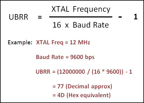
UBRR register value is calculated by the following formula:
UBRR register value is calculated by the following formula:


Fig. 14: Formula of UBRR register to set Baud rate in USART
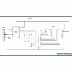
The Connection of MAX232 and ATmega16 is shown in the circuit diagram. The MAX232 is used for level conversion. The reader can refer the component section for further details on MAX 232.The T1IN (pin11) of Max232 is connected to Tx (pin15) of AVR and R1IN(pin12) is connected to Rx(pin14) of AVR. The HyperTerminal software is used to send data to microcontroller via COM port.
Code Explanation:
Step 1: First step is to select the Baud rate. Baud rate of two devices must match or else they will not be able to synchronize with each other.
#define USART_BAUDRATE 9600
Step2: To set a particular Baud Rate in ATmega16, write the corresponding UDRR value. The UDRR value is calculated by using the formula
#define BAUD_PRESCALE (((F_CPU / (USART_BAUDRATE * 16UL))) - 1)
Step3: To initialize the USART
i. Turn on transmission and reception circuitry.
ii. Select the number of stop bits.
iii. Set the size of data.
iv. Load the value of UBRR to set the baud rate.
void usart_init()
{
UCSRB |= (1 << RXEN) | (1 << TXEN); // Turn on the transmission and reception circuitry
UCSRC |= (1 << URSEL) | (1<<USBS) | (1 << UCSZ0) | (1 << UCSZ1);
// Use 8-bit character sizes
UBRRL = BAUD_PRESCALE;
// Load lower 8-bits of the baud rate value into the low byte of the UBRR register
UBRRH = (BAUD_PRESCALE >> 8); // Load upper 8-bits of the baud rate value..
// into the high byte of the UBRR register
}
Step4: Get the data from USART
Monitor the status of RXC (receiver complete) flag . RXC becomes high when it receives the stop bit signal. So if RXC is high it means that the data is loaded into UDR register. Collect the data from UDR or else it might get lost or overwritten with the next incoming data.
unsigned int usart_getch()
{
while ((UCSRA & (1 << RXC)) == 0);
// Do nothing until data has been received and is ready to be read from UDR
return(UDR); // return the byte
}
Circuit:

Code:
// Program to receive data from USART and displaying it on LCD
/*
Receive data from serial port and display it on LCD
LCD DATA port----PORT A
ctrl port------PORT B
rs-------PB0
rw-------PB1
en-------PB2
using external clock frequency 12MHz
*/
#define F_CPU 12000000UL
#define USART_BAUDRATE 9600 // Baud Rate value
#define BAUD_PRESCALE (((F_CPU / (USART_BAUDRATE * 16UL))) - 1)
#include<avr/io.h>
#include<util/delay.h>
#define LCD_DATA PORTA //LCD data port
#define ctrl PORTB
#define en PB2 // enable signal
#define rw PB1 // read/write signal
#define rs PB0 // register select signal
void LCD_cmd(unsigned char cmd);
void init_LCD(void);
void LCD_write(unsigned char data);
void LCD_clear();
void usart_init();
void usart_putch(unsigned char send);
unsigned int usart_getch();
int main()
{
unsigned char value;
DDRA=0xff; // LCD_DATA port as output port
DDRB=0x07; // signal as out put
init_LCD(); //initialization of LCD
_delay_ms(50); // delay of 50 milli seconds
usart_init(); // initialization of USART
while(1)
{
value=usart_getch(); // Call a function to get data from serial port
LCD_cmd(0xC0); // to go in second line and zeroth position on LCD
LCD_write(value); // write data to LCD
}
return 0;
}
void init_LCD(void)
{
LCD_cmd(0x38); // initialization of 16X2 LCD in 8bit mode
_delay_ms(1);
LCD_cmd(0x01); // clear LCD
_delay_ms(1);
LCD_cmd(0x0E); // cursor ON
_delay_ms(1);
LCD_cmd(0x80); // ---8 go to first line and --0 is for 0th position
_delay_ms(1);
return;
}
void LCD_cmd(unsigned char cmd)
{
LCD_DATA=cmd;
ctrl =(0<<rs)|(0<<rw)|(1<<en);
_delay_ms(1);
ctrl =(0<<rs)|(0<<rw)|(0<<en);
_delay_ms(50);
return;
}
void LCD_write(unsigned char data)
{
LCD_DATA= data;
ctrl = (1<<rs)|(0<<rw)|(1<<en);
_delay_ms(1);
ctrl = (1<<rs)|(0<<rw)|(0<<en);
_delay_ms(50);
return ;
}
void usart_init()
{
UCSRB |= (1 << RXEN) | (1 << TXEN); // Turn on the transmission and reception circuitry
UCSRC |= (1 << URSEL) | (1<<USBS) | (1 << UCSZ0) | (1 << UCSZ1);
// Use 8-bit character sizes
UBRRL = BAUD_PRESCALE;
// Load lower 8-bits of the baud rate value into the low byte of the UBRR register
UBRRH = (BAUD_PRESCALE >> 8); // Load upper 8-bits of the baud rate value..
// into the high byte of the UBRR register
}
unsigned int usart_getch()
{
while ((UCSRA & (1 << RXC)) == 0);
// Do nothing until data has been received and is ready to be read from UDR
return(UDR); // return the byte
}
Không có nhận xét nào:
Đăng nhận xét