Did you know that most of the thefts at home happen when it is empty? But not everyone is rich enough to hire a security for their house and at the same time they themselves cannot be at home 24x7. Now what if there is a system which alerts you about an intruder through a text message? The following tutorial discusses how to make you own intruder alerting system.
Components Required
1. PIR Sensor
2. ATMega16 Development board
3. LCD board
4. SIM 300/900 GSM Module
5. 12V/2A Power Supply
6. SIM card with balance (or at least message offer maybe)
7. A PC or a Laptop (Optional. Needed in case of debugging)
Initial Setup and Testing of GSM modem
If you are already familiar with a GSM Modem then you may skip this step. This part of the tutorial is for the beginners.
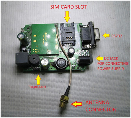
Step 1: Inserting the SIM


Step 2: Attach the antenna to the SMA connector shown in the picture

Step 3: Attaching the power supply and Powering the modem

Step 4: Attaching the RS232 to USB Converter


Step 5: Testing the modem through a PC/ Laptop

Once you have connected the modem and PC, you can open your default serial communication software on your PC and start sending AT commands to the modem and observing its replies.

As you can see from the above screen shot, when I sent “AT”, the modem sends back “OK”. Similarly after every correct command the modem would reply with necessary parameters and an “OK”. If you enter any wrong or inappropriate command then the modem says “ERROR”
Why PIR sensor?
Well PIR sensors are designed to detect human beings specifically and so there is very low chance for a false alarm. You can use Infrared TX-RX pair also but their range is lesser and there is more probability for false alarm. Say, for example a cat comes close to the sensor’s field range or if there is a light variation in the room where you fixed the sensor. In both cases the IR sensor would react and generate a false alarm but PIR sensor will remain immune.
Amplifier Circuit & Code Explanation
Since the output signal from the PIR is very weak we use a simple amplifier circuit to get a stronger output.

Code Explanation
- Initialize the USART and LCD functions
- Assign PB0 as input pin and put it in HIGH state
- Enter an infinite loop
- Check the status of PB0 pin. If it goes low, then go to Notify() function
Notify() function sends the following commands:
Command
|
Description
|
AT+CMGF=1<CR>
|
To set the Message Format into Text mode. 1 is for Text mode and 0 is for PDU mode.
|
AT+CMGS=”+919876543210”<CR>
>Motion Detected<Ctrl+Z>
|
Send the text “Motion Detected” to the number given inside the quotes.
|
Here <CR> is nothing but the special character ‘\r’ whose ASCII code is 13. Ctrl+Z has a ASCII code of 26
Testing & Troubleshooting
Testing the System
1. Connect everything according to the circuit diagram after burning the program into the microcontroller.
NOTE: TX of modem <-> RX of controller
RX of modem <->TX of controller
GND of modem <-> GND of controller
2. Place the PIR sensor facing away from you before you power ON the system.
3. Now power ON the system.
4. Wait a while for the SIM to get registered to the Network. It may take from 10-50 seconds for that. (You can know if it is registered or not by observing the network LED status. If the blinking rate is very low then it means the SIM is ready now)
5. Wave your hand in front of the PIR sensor. Now you should see the LED attached to the amplifier circuit light up and the LCD displaying “Motion Detected”. Within few seconds, you should get a message to the number you have given in the program. Like this:

Troubleshooting
A. The SIM is not getting registered to the network
Possible Reasons:
1. The signal strength of the modem maybe weak. Make sure the Antenna is fixed firmly
2. Make sure the Network provider gives enough signal strength in your area and there are no jammers around.
3. Make sure the SIM card is valid.
B. Message not received by the user’s phone
Possible Reasons:
1. Check your program and see if you gave the right phone number or not.
2. See if the user’s phone has enough signal strength to receive a message.
3. You waved it too soon after powering ON the device. Remember the SIM card takes time to get registered to a Network.
4. There is no balance in the SIM card. Make sure the SIM card has some balance or a message offer.
Circuit:

Code:
Main Program

/*
 * sim1way.c
 *
 * Created: 1/12/2014 3:14:58 PM
 *  Author: Ganesh Selvaraj
 */
#define F_CPU 16000000UL
#define USART_BAUDRATE 9600
#define BAUD_PRESCALE (((F_CPU / (USART_BAUDRATE * 16UL))) - 1)
#define PIR (PINB & 0b00000001)
#include<avr/io.h>
#include<util/delay.h>
#include "lcd.h"
void BlueInit()
{
UCSRB |= (1 << RXEN) | (1 << TXEN);   // Enable transmission and reception
UCSRC |= (1 << URSEL) | (1<<USBS) | (1 << UCSZ0) | (1 << UCSZ1);
// Use 8-bit character sizes
UBRRL = BAUD_PRESCALE;
UBRRH = (BAUD_PRESCALE >> 8);
}
void BlueWrChar(unsigned char d)
{
while ((UCSRA & (1 << UDRE)) == 0); // wait till UDR is ready
UDR = d; // send data
}
unsigned int BlueRdChar()
{
while ((UCSRA & (1 << RXC)) == 0); // wait until data has been received
return(UDR); // return the byte
}
void BlueWrString(const char *msg)
{
while(*msg!='\0')
{
BlueWrChar(*msg);
msg++;
}
BlueWrChar(13);
}
void BlueWrCMD(const char *msg)
{
while(*msg!='\0')
{
BlueWrChar(*msg);
msg++;
}
}
void Waiting(int j) // simple delay function
{
uint8_t i;
for(i=0;i<j;i++)
_delay_ms(200);
}
void Notify()
{
BlueWrString("AT+CMGF=1");
Waiting(1);
BlueWrCMD("AT+CMGS=");
BlueWrChar(34);  // "
BlueWrCMD("+91xxxxxxxxxx"); // Replace the 'x's with a valid Phone number
BlueWrChar(34);
BlueWrChar('\0');
BlueWrChar(13); // <CR> OR \r
Waiting(1);
BlueWrCMD("MOTION DETECTED");
BlueWrChar(26);  // CTRL+Z
Waiting(15);
clrscr();
LCD_write_string("  MESSAGE SENT  ");
Waiting(30);
}
int main()
{
DDRB=0b11111110;
PORTB=0b00000001;
BlueInit(); // initialization of USART
lcd_init();
LCD_write_string("   GSM BASED    ");
gotoxy(1,0);
LCD_write_string("INTRUDER ALERTER");
Waiting(10);
clrscr();
gotoxy(0,7);
LCD_write_string("BY");
gotoxy(1,0);
LCD_write_string("GANESH SELVARAJ");
BlueWrString("AT");
Waiting(10);
clrscr();
LCD_write_string(" SYSTEM ACTIVE!");
while(1)
{
if(PIR==0)
{
clrscr();
LCD_write_string("MOTION DETECTED");
Notify();
Waiting(10);
clrscr();
LCD_write_string(" SYSTEM ACTIVE!");
}
}
return 0;
}


LCD Program


#ifndef LCD_H_
#define LCD_H_
#define rs PA7
#define rw PA6
#define en PA4
#define F_CPU 16000000UL
#include<avr/io.h>
#include<util/delay.h>
#include<inttypes.h>
void lcd_init();
void dis_cmd(char);
void dis_data(char);
void lcdcmd(char);
void lcddata(char);
void clrscr();
void gotoxy(char,char);
void LCD_write_string(const char *);
void LCD_write_string(const char *str) //store address value of the string in pointer *str
{
int i=0;
while(str[i]!='\0') // loop will go on till the NULL character inthe string
{
dis_data(str[i]); // sending data on LCD byte by byte
i++;
}
return;
}
void lcd_init() // function for initialize
{
DDRA=0xFF;
dis_cmd(0x02); // to initialize LCD in 4-bit mode.
dis_cmd(0x28); //to initialize LCD in 2 lines, 5X7 dots and 4bit mode.
dis_cmd(0x0C);
dis_cmd(0x06);
dis_cmd(0x80); // 8-- 1st line 0- 0TH position
}
void dis_cmd(char cmd_value)
{
char cmd_value1;
cmd_value1 = ((cmd_value>>4) & 0x0F); //shift 4-bit and mask
lcdcmd(cmd_value1); // send to LCD
cmd_value1 = cmd_value & 0x0F; //mask lower nibble because PA4-PA7 pins are used.
lcdcmd(cmd_value1); // send to LCD
}
void dis_data(char data_value)
{
char data_value1;
data_value1=((data_value>>4)&0x0F);
lcddata(data_value1);
data_value1=data_value&0x0F;
lcddata(data_value1);
}
void lcdcmd(char cmdout)
{
PORTA=cmdout;
PORTA&=~(1<<rs);
PORTA&=~(1<<rw);
PORTA|=(1<<en);
_delay_ms(1);
PORTA&=~(1<<en);
}
void lcddata(char dataout)
{
PORTA=dataout;
PORTA|=(1<<rs);
PORTA&=~(1<<rw);
PORTA|=(1<<en);
_delay_ms(1);
PORTA&=~(1<<en);
}
void clrscr()
{
_delay_ms(100);
dis_cmd(0x01);
_delay_ms(10);
}
void gotoxy(char a,char b)
{
if(a==0)  a=0b10000000;
else if(a==1) a=0b11000000;
dis_cmd(a|b);
}
#endif


Không có nhận xét nào:
Đăng nhận xét