Hướng dẫn sử dụng Cân điện tử Fujihatsu FTC-01
#candientu, #fujihatsu, #candientufujihatsu #candientu, #candientufujhatsu, #fujihatsu, #canhaiduong, #cannamdinh, #canhanam, #canhungyen, #canthaibinh, #canninhbinh, #canbacninh, #csnbacgiang, #canhaiphong, #canquangninh, #candientuhaiduong, #candientuhanam, #candientunamdinh, #candientuhungyen, #candientuthaibinh, #candientuquangninh, #candientubacninh, #candientubacgiang, #candientuninhbinh, #candientuhaiphong
https://www.facebook.com/Fujihatsu-Vi%E1%BB%87t-Nam-110364470474066/
Thứ Bảy, 18 tháng 1, 2020
Sự thật về cân điện tử chống nước Fujihatsu FTC-02
Sự thật về cân điện tử chống nước Fujihatsu FTC-02
https://www.youtube.com/watch?v=rDeQHbGJHk0
#canchongnuoc, #candientuchongnuoc, #candientu, #candientufujhatsu, #fujihatsu #candientu, #candientufujhatsu, #fujihatsu, #canhaiduong, #cannamdinh, #canhanam, #canhungyen, #canthaibinh, #canninhbinh, #canbacninh, #csnbacgiang, #canhaiphong, #canquangninh, #candientuhaiduong, #candientuhanam, #candientunamdinh, #candientuhungyen, #candientuthaibinh, #candientuquangninh, #candientubacninh, #candientubacgiang, #candientuninhbinh, #candientuhaiphong
Thứ Sáu, 14 tháng 12, 2018
Interfacing Serial Bluetooth Modem with Computer using ATmega16
This article would give you a general idea about how to setup and interface any Bluetooth modem with your computer. There are many types of Bluetooth modems available in market, which vary in quality, cost, range, etc. Some of the well known Serial Bluetooth modems are AUBTM, BLUESMIRF, RN-41, HC-05 and HC-04.
I would be using the last one i.e. the cheap Chinese Bluetooth module. It has limited functions and it can only work in slave mode. (Remember: Two slave modules cannot directly communicate to each other so be careful when you buy them.) The top range modules have a facility to work in both MASTER and SLAVE modes. It is Class 3 module so it range is very low. (Class 2 has a range of 10 meters and Class 1 has a range of 100 meters.)
Step 1: Power ON the Serial Bluetooth Modem and also turn ON the Bluetooth on your computer. You should see the below icon at the right hand corner of your computer.

Step 2: Right-click on the Bluetooth Icon and you should see the below given option. Click on “Add a Device” option.

Once you click that option you computer initiates a Bluetooth connection and starts searching for any nearby Bluetooth enable devices.
Step 3: You should next see this type of dialog box which will be loaded with the active Bluetooth devices in the surroundings. You should see something like”HC-04” or “HC-05” or “AUBTM” or some other similar names. Click on the device name and click “Next” then.
Note: I already renamed my Serial Bluetooth Modem to “RR_WIRELESS” so that’s what is appearing in the list there. Refer your modem’s datasheet to know how to rename the module’s Bluetooth Name.

Step 4: Next, the computer would ask you whether you want to create a pairing code or enter device’s pairing code or to pair without using code. Click on “Enter the device’s pairing code”. Generally, all modems would have a default pairing code (Even cheap Chinese modems). So you have no other alternative to pair the device with your computer.
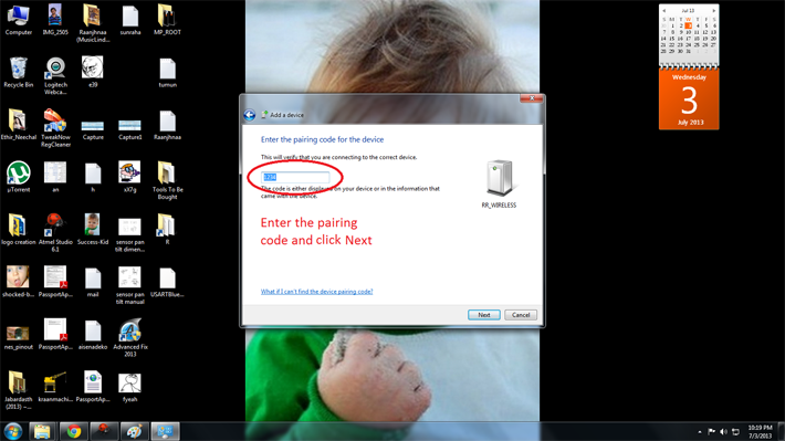
Step 5: Enter your device’s pairing code as shown below. Refer your modem’s datasheet to know the default pairing code of your device. It is generally “0000” or “1234”. In my case it was “1234”. Enter the code and click “Next”.

As soon as you click “Next” you should see notifications at your right hand corner saying “Device drivers being installed”.
Step 6: If everything goes well in the end you should see a pop-up similar to one shown below. Note down the COM Port numbers since we’ll be using those only to establish future connections between your modem and your PC.

RUNNING THE DEMO PROJECT:
We are done with configuring the Serial Bluetooth Modem with the computer. Next we’ll see how to run the demo program.
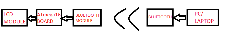
Block Diagram
BLOCK DIAGRAM:
Step 1: Burn the attached “demo.hex” file into your ATMega16 microcontroller using the necessary programmer and software.
Step 2: Connect the LCD module and Bluetooth modem to the Development Board. Note that TX pin of modem is connected to RX pin of the microcontroller and RX pin of modem to the TX pin of the controller.
Step 3: Now you’ll need Serial Communication software to communicate with the ATmega16 through Bluetooth. If you are a Windows XP user then you would have default software called “HyperTerminal” in your computer. But if you are a windows 7 user like me then you need a third party software. There are various free third party software solutions available in internet like RealTerm, Putty and TeraTerm. Or you can buy the HyperTerminal Private edition too.
Note: I’m using a Windows Form Application which I created myself using Visual Studio 2012. I will explain you how to make one by yourself in the next tutorial.
Whichever software you use, these would be the general steps to be followed while establishing the connections.
Turn ON the controller board and Bluetooth in your computer.
Open the Serial Port software. There would be many options and configuration settings. Don’t modify any of them unnecessarily. Just change the below given settings.
Go to the Port Tab and set it as follows.
Baud: 9600
Port: <The port we previously noted down during first time setup>
Data bits: 8
Parity: None
Stop bits: 1
Hardware Flow Control: None
The below image shows you a screenshot of the configurations .

Now type something on the screen and you should see the same text being displayed on the LCD also which is connected to the controller board.
Working of project code
Description and Working of project code
The code basically involves two parts.
1. LCD Interfacing code
2. USART (Universal Synchronous Asynchronous Receiver Transmitter) implementation code
LCD Interfacing code
Here are the functions involved in LCD interfacing and their purposes
Function Name
|
Purpose of the Function
|
LCDClear()
|
Clears the screen of the LCD display.
|
LCDWriteString(“<string>”)
|
Displays the <string> on the LCD display.
|
LCDWriteStringXY(x,y,”<string>”)
|
Goes to position x, y of the LCD display and displays the <string>
|
LCDData(x)
|
Displays the character stored in variable ‘x’ which is of “char” type.
|
LCDInit()
|
Initializes the LCD.
|
USART implementation code
This is responsible for establishing a serial connection between the microcontroller and PC/Laptop (via Bluetooth)
Here are the functions involved in USART Implementation and their purposes
Function Name
|
Purpose of the Function
|
BlueRdChar()
|
Reads the data available at RX pin of the controller. It waits till any data is available.
|
BlueWrChar(data)
|
Writes the character stored in variable “data” into USART line which in turn transmits it to TX pin of controller.
|
BlueInit(n)
|
Initializes the USART function with required baud rate set by the integer ‘n’
|
Working of Code (Algorithm)
Step 1: Initialize the LCD function and USART function with 9600 baud rate.
Step 2: Displays some message on LCD screen and after some delay time clear it.
Step 3: Enter an Infinite Loop.
Step 4: Display “Receiving Data….”.
Step 5: Wait for a character to be available at RX pin of the controller using the BlueRdChar() function. If character is available, go to step 6 elsewait.
Step 6: Store the incoming character in the variable named ‘data’.
Step 7: Write the character stored at ‘data’ into the USART line i.e. transmit it to the TX pin of the controller using BlueWrChar(data) function.
Step 8: Write the same character onto the bottom line of the LCD display using LCDData(data) function. If the bottom line is filled, clear the Display using LCDClear() and go to step 4 else go to step 5.
Circuit:

Code:
/*
* USARTBlue.c
*
* Created: 7/1/2013 10:50:05 PM
* Author: GANESH SELVARAJ
*/
#define F_CPU 16000000UL
#include <avr/io.h>
#include <inttypes.h>
#include "lib/LCD/lcd.h"
void BlueInit(uint16_t ubrr_value) //This function is used to initialize the USART at a given UBRR value
{
//Set Baud rate
UBRRL = ubrr_value;
UBRRH = (ubrr_value>>8);
/*We Set Frame Format as
>> Asynchronous mode
>> No Parity
>> 1 StopBit
>> char size 8
*/
UCSRC=(1<<URSEL)|(3<<UCSZ0);
//Enable The RX receiver and TX transmitter
UCSRB=(1<<RXEN)|(1<<TXEN);
}
char BlueRdChar() // function used to read data from USART line. It waits till any data is available
{
while(!(UCSRA & (1<<RXC)))
{
}
return UDR;
}
void BlueWrChar(char data) // function writes the character in 'data' into USART and then transmits it to PC via TX line
{
while(!(UCSRA & (1<<UDRE)))
{
}
UDR=data;
}
void Waiting(int j) // simple delay function
{
uint8_t i;
for(i=0;i<j;i++)
_delay_ms(200);
}
int main()
{
char data;
int i;
/*First Initialize the USART with baud rate = 9600bps
for Baud rate = 9600bps
UBRR value = 103
*/
BlueInit(103); //UBRR = 103
//Initialize LCD module
LCDInit(LS_BLINK|LS_ULINE);
//Clear the screen
LCDClear();
LCDWriteString("BLUETOOTH MODULE");
LCDWriteStringXY(0,1," INTERFACING ");
Waiting(5);
LCDClear();
LCDWriteString(" By ");
LCDWriteStringXY(0,1,"GANESH SELVARAJ");
Waiting(5);
LCDClear();
//Loop forever
while(1)
{
LCDClear();
LCDWriteString("Receiving Data..");
for (i=0;i<=15;i++)
{
data=BlueRdChar();
BlueWrChar(data);
LCDGotoXY(i,1);
LCDData(data);
}
Waiting(2);
}
return 0;
}
/*############################################################
A easy to use library for interfacing standard 16x2 character
LCD modules with AVR series of MCUs
--------------------------------------------------------------
##############################################################*/
#include <avr/io.h>
#include <inttypes.h>
#ifndef F_CPU
#define F_CPU 12000000UL
#endif
#include <util/delay.h>
#include "lcd.h"
#define LCD_DATA_PORT PORT(LCD_DATA)
#define LCD_E_PORT PORT(LCD_E)
#define LCD_RS_PORT PORT(LCD_RS)
#define LCD_RW_PORT PORT(LCD_RW)
#define LCD_DATA_DDR DDR(LCD_DATA)
#define LCD_E_DDR DDR(LCD_E)
#define LCD_RS_DDR DDR(LCD_RS)
#define LCD_RW_DDR DDR(LCD_RW)
#define LCD_DATA_PINPIN(LCD_DATA)
#define SET_E() (LCD_E_PORT|=(1<<LCD_E_POS))
#define SET_RS() (LCD_RS_PORT|=(1<<LCD_RS_POS))
#define SET_RW() (LCD_RW_PORT|=(1<<LCD_RW_POS))
#define CLEAR_E() (LCD_E_PORT&=(~(1<<LCD_E_POS)))
#define CLEAR_RS() (LCD_RS_PORT&=(~(1<<LCD_RS_POS)))
#define CLEAR_RW() (LCD_RW_PORT&=(~(1<<LCD_RW_POS)))
void LCDByte(uint8_t c,uint8_t isdata)
{
//Sends a byte to the LCD in 4bit mode
//cmd=0 for data
//cmd=1 for command
//NOTE: THIS FUNCTION RETURS ONLY WHEN LCD HAS PROCESSED THE COMMAND
uint8_t hn,ln;//Nibbles
uint8_t temp;
hn=c>>4;
ln=(c & 0x0F);
if(isdata==0)
CLEAR_RS();
else
SET_RS();
_delay_us(0.500);//tAS
SET_E();
//Send high nibble
temp=(LCD_DATA_PORT & 0XF0)|(hn);
LCD_DATA_PORT=temp;
_delay_us(1);//tEH
//Now data lines are stable pull E low for transmission
CLEAR_E();
_delay_us(1);
//Send the lower nibble
SET_E();
temp=(LCD_DATA_PORT & 0XF0)|(ln);
LCD_DATA_PORT=temp;
_delay_us(1);//tEH
//SEND
CLEAR_E();
_delay_us(1);//tEL
LCDBusyLoop();
}
void LCDBusyLoop()
{
//This function waits till lcd is BUSY
uint8_t busy,status=0x00,temp;
//Change Port to input type because we are reading data
LCD_DATA_DDR&=0xF0;
//change LCD mode
SET_RW();//Read mode
CLEAR_RS();//Read status
//Let the RW/RS lines stabilize
_delay_us(0.5);//tAS
do
{
SET_E();
//Wait tDA for data to become available
_delay_us(0.5);
status=LCD_DATA_PIN;
status=status<<4;
_delay_us(0.5);
//Pull E low
CLEAR_E();
_delay_us(1);//tEL
SET_E();
_delay_us(0.5);
temp=LCD_DATA_PIN;
temp&=0x0F;
status=status|temp;
busy=status & 0b10000000;
_delay_us(0.5);
CLEAR_E();
_delay_us(1);//tEL
}while(busy);
CLEAR_RW();//write mode
//Change Port to output
LCD_DATA_DDR|=0x0F;
}
void LCDInit(uint8_t style)
{
/*****************************************************************
This function Initializes the lcd module
must be called before calling lcd related functions
Arguments:
style = LS_BLINK,LS_ULINE(can be "OR"ed for combination)
LS_BLINK :The cursor is blinking type
LS_ULINE :Cursor is "underline" type else "block" type
*****************************************************************/
//After power on Wait for LCD to Initialize
_delay_ms(30);
//Set IO Ports
LCD_DATA_DDR|=(0x0F);
LCD_E_DDR|=(1<<LCD_E_POS);
LCD_RS_DDR|=(1<<LCD_RS_POS);
LCD_RW_DDR|=(1<<LCD_RW_POS);
LCD_DATA_PORT&=0XF0;
CLEAR_E();
CLEAR_RW();
CLEAR_RS();
//Set 4-bit mode
_delay_us(0.3);//tAS
SET_E();
LCD_DATA_PORT|=(0b00000010); //[B] To transfer 0b00100000 i was using LCD_DATA_PORT|=0b00100000
_delay_us(1);
CLEAR_E();
_delay_us(1);
//Wait for LCD to execute the Functionset Command
LCDBusyLoop(); //[B] Forgot this delay
//Now the LCD is in 4-bit mode
LCDCmd(0b00001100|style);//Display On
LCDCmd(0b00101000);//function set 4-bit,2 line 5x7 dot format
}
void LCDWriteString(const char *msg)
{
/*****************************************************************
This function Writes a given string to lcd at the current cursor
location.
Arguments:
msg: a null terminated string to print
*****************************************************************/
while(*msg!='\0')
{
LCDData(*msg);
msg++;
}
}
void LCDWriteInt(int val,unsigned int field_length)
{
/***************************************************************
This function writes a integer type value to LCD module
Arguments:
1)int val: Value to print
2)unsigned int field_length :total length of field in which the value is printed
must be between 1-5 if it is -1 the field length is no of digits in the val
****************************************************************/
char str[5]={0,0,0,0,0};
int i=4,j=0;
while(val)
{
str[i]=val%10;
val=val/10;
i--;
}
if(field_length==-1)
while(str[j]==0) j++;
else
j=5-field_length;
if(val<0) LCDData('-');
for(i=j;i<5;i++)
{
LCDData(48+str[i]);
}
}
void LCDGotoXY(uint8_t x,uint8_t y)
{
if(x<40)
{
if(y) x|=0b01000000;
x|=0b10000000;
LCDCmd(x);
}
}
//############################# lcd.h ###########################//
#include <avr/io.h>
#ifndef F_CPU
#define F_CPU 12000000UL
#endif
#include <util/delay.h>
#include "myutils.h"
#ifndef _LCD_H
#define _LCD_H
/*_________________________________________________________________________________________*/
/************************************************
LCD CONNECTIONS
*************************************************/
#define LCD_DATA A//Port PB0-PB3 are connected to D4-D7
#define LCD_E A //Enable/strobe signal
#define LCD_E_POSPA4//Position of enable in above port
#define LCD_RS A
#define LCD_RS_POS PA7
#define LCD_RW A
#define LCD_RW_POS PA6
//************************************************
#define LS_BLINK 0B00000001
#define LS_ULINE 0B00000010
/***************************************************
F U N C T I O N S
****************************************************/
void LCDInit(uint8_t style);
void LCDWriteString(const char *msg);
void LCDWriteInt(int val,unsigned int field_length);
void LCDGotoXY(uint8_t x,uint8_t y);
//Low level
void LCDByte(uint8_t,uint8_t);
#define LCDCmd(c) (LCDByte(c,0))
#define LCDData(d) (LCDByte(d,1))
void LCDBusyLoop();
/**************************************************
F U N C T I O N S E N D
****************************************************/
/***************************************************
M A C R O S
***************************************************/
#define LCDClear() LCDCmd(0b00000001)
#define LCDHome() LCDCmd(0b00000010);
#define LCDWriteStringXY(x,y,msg) {\
LCDGotoXY(x,y);\
LCDWriteString(msg);\
}
#define LCDWriteIntXY(x,y,val,fl) {\
LCDGotoXY(x,y);\
LCDWriteInt(val,fl);\
}
/***************************************************/
/*_________________________________________________________________________________________*/
#endif
/############### Myutils.h ###################/
#ifndef MYUTILS_H
#define MYUTILS_H
#define _CONCAT(a,b) a##b
#define PORT(x) _CONCAT(PORT,x)
#define PIN(x) _CONCAT(PIN,x)
#define DDR(x) _CONCAT(DDR,x)
#endif
Đăng ký:
Nhận xét (Atom)
Bài đăng phổ biến
-
 Hướng dẫn này là về ADC trong AVR vi điều khiển ATmega32A. ADC là viết tắt của analog để chuyển đổi kỹ thuật số cho phép chúng ta tương tác...
 -
In this ATMega16 AVR project we will be designing and implementing a digital clock with the aid of a atmel AVR ATMega16 microcontro...
-
Developed By: Akshay Daga Communication between two entities is important for the information flow to take place. In gener...
-
AVR microcontrollers are the advanced microcontrollers . From 1996 onwards these are come into existence. In AVR family there are so m...
-
In many application of controlling robotic gadget it becomes quite hard and complicated when there comes the part of controlling it wit...
-
Developed By: Akshay Daga Pulse Width Modulation is well known technique for controlling power electronics devices like SC...
-
Developed By: Akshay Daga JTAG stands for “Joint Test Action Group” which was standardized as the IEEE 1149.1 Standard T...
-
The circuit presented here demonstrates how to generate Audible Frequency from an AVR Microcontroller . The output of Microcontroller ...
-
Requirements AtMega 16 IC /development board 2. 3-Axis accelerometer 3. LCD screen 16X2 (for displaying X, Y and Z data) Descri...
-
Developed By: Akshay Daga Servo motors find huge applications in industries in the field of automation, control & rob...


