Developed By:
Akshay Daga
A microcontroller is a device which has an inbuilt processor surrounded by few dedicated hardware modules. Once the microcontroller initializes them they start operating on their own. In case of an ADC it will do the sampling and digital to analog conversion all by itself and keep the converted data in its buffer so that the microcontroller can read that later. The advantage of this kind of implementation is that the microcontroller is free to do other tasks during that time and hence increase the overall efficiency. That was the case of hardware modules or peripherals inside a microcontroller which increases the processing efficiency of the built in processor. The efficiency can increase even more if the external hardware attached to the microcontroller can also does lot more tasks by their own without depending the microcontroller. The hardware may or may not contain another processor so that it can perform certain predetermined task after initialized by the microcontroller.
An example for such a device is the serial LCD scrolling display. Once the data to be displayed in scrolling manner is received from the microcontroller, it will start the operation by its own and perform the scrolling process. This project explains interfacing of LCD MODULE with any type of controller using single serial receiving pin. In this mode only one pin is used for sending data. This scrolling display mode has the advantage over the 8-bit mode as it uses only a single pin. The remaining pins of the controller are available for normal use and the valuable processing power required to scroll the data can be used for any other purpose.

The project is discussed in two parts.
Part 1: To Create LCD module
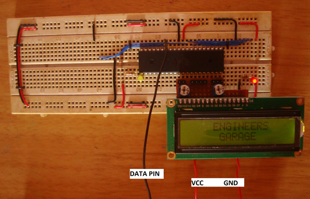
In part one LCD module is created using AVR controller and 16x2 alphanumeric LCD display. The controller ATMEGA16 controls the LCD. The programmed code dumped permanently to this atmega16 is controlling the LCD module. A single receiving pin (RXD -14) of ATMEGA16 is the only input of this LCD module. The data received by serial communication is displayed on the LCD module in a scrolling manner.

Fig. 2: Circuit set up of LCD Module built using AVR controller and 16x2 alphanumeric LCD display
Part2: Interfacing the LCD module using any other microcontroller.
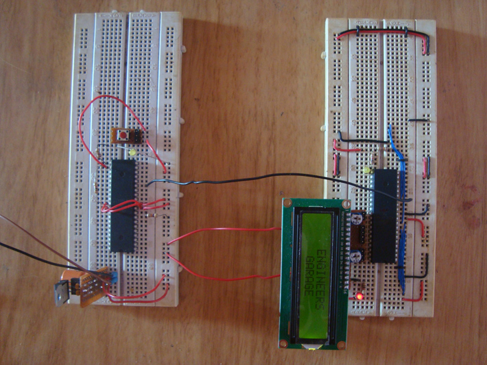
In part two the controller used is in our project is another AVR chip. The data send to the LCD module via serial transmission pin (TXD-15).A switch demonstrated in our project give the input to the controller.

Fig. 3: Interfacing the LCD module with second AVR microcontroller for
A predefined text is transmitted to the LCD module upon every press of the switch. Whatever the text sends, the data will be scrolled in the LCD module.

Fig. 4: Data communication between LCD Module and AVR via serial transmission circuit setup on breadboard
From this demonstration it can be noticed that 8 data pins and 3 control pins of the microcontroller can be saved. Those saved pins can be used for any other purpose.
Circuit description:
Connections of LCD with ATmega16 are shown in circuit diagram. In 4-bit mode, the Data lines must be connected with D4, D5, D6 and D7 pins of LCD module.
Circuit:
Code:
#define F_CPU 8000000
#include <avr/io.h>
#include <util/delay.h>
#include <avr/interrupt.h>
#include <avr/eeprom.h>
#include "usart.h"
void switch_init ( void );
int main ( void )
{
usart_init ();
switch_init ();
while ( 1 )
{
PORTD &= 0x7F;
_delay_ms ( 2000 );
PORTD |= 0x80;
while ( 0x0F == ( PINC & 0x0F ) ); // wait till any key is pressed
_delay_ms ( 50 );
usart_send_string ( "This is a demonstration of single line LCD scrolling display module interfacing
by Engineers Garage !!!\n" );
_delay_ms ( 500 );
}
}
void switch_init ( void )
{
cli();
DDRC &= 0xE0;
PORTC = 0xFF;
DDRD |= 0x80;
PORTD |= 0x80;
}
#define _USART_H #ifndef F_CPU #define F_CPU 8000000 #endif #define USART_BAUDRATE 9600 #define BAUD_PRESCALE (((F_CPU / (USART_BAUDRATE * 16UL))) - 1) #include<avr/io.h> #include<util/delay.h> #include <stdio.h> void usart_init(); void usart_putch(unsigned char send); unsigned int usart_getch(); void usart_send_string(const char* data); int uart_print(char c, FILE *stream); FILE uart_out = FDEV_SETUP_STREAM(uart_print, NULL, _FDEV_SETUP_WRITE); int uart_print(char c, FILE *stream) { if (c == '\n') uart_print('\r', stream); loop_until_bit_is_set(UCSRA, UDRE); UDR = c; return 0; } void usart_init () { UCSRB |= (1<<RXCIE) | (1 << RXEN) | (1 << TXEN); // Turn on the transmission reception .. // circuitry and receiver interrupt UCSRC |= (1 << URSEL) | (1 << UCSZ0) | (1 << UCSZ1); // Use 8-bit character sizes UBRRL = BAUD_PRESCALE; // Load lower 8-bits of the baud rate value.. // into the low byte of the UBRR register UBRRH = (BAUD_PRESCALE >> 8); // Load upper 8-bits of the baud rate value.. // into the high byte of the UBRR register stdout = &uart_out; } void usart_putch(unsigned char send) { while ((UCSRA & (1 << UDRE)) == 0); // Do nothing until UDR is ready.. // for more data to be written to it UDR = send; // Send the byte } unsigned int usart_getch() { while ((UCSRA & (1 << RXC)) == 0); // Do nothing until data have been received and is ready to be read from UDR return(UDR); // return the byte } void usart_send_string(const char* data) { for(; *data; data ++) usart_putch(*data); } #endif
Code 2:
#ifndef _LCD_H #define _LCD_H #ifndef F_CPU #define F_CPU 8000000 #endif #include<avr/io.h> #include<util/delay.h> #include<inttypes.h> #include <stdio.h> #include <string.h> #define rs PA0 #define rw PA1 #define en PA2 void lcd_init(); void dis_cmd(char); void dis_data(char); void lcdcmd(char); void lcddata(char); void lcd_clear(void); void lcd_2nd_line(void); void lcd_1st_line(void); void lcd_string(const char *data); int lcd_print(char c, FILE *stream); int lcd_scroll(const char *data); FILE lcd_out = FDEV_SETUP_STREAM(lcd_print, NULL, _FDEV_SETUP_WRITE); char disp_beg [] = " "; int lcd_print(char c, FILE *stream) { if('\n' == c) lcd_2nd_line(); else dis_data(c); return 0; } #define F_CPU 8000000 #include <avr/io.h> #include <util/delay.h> #include <stdio.h> #include <avr/interrupt.h> #include "lcd.h" #include "usart.h" char A [ 150 ]; char B [ 150 ]; int main ( void ) { int i; usart_init (); cli(); lcd_init (); printf ( " ENGINEERS "); printf ( "\n GARAGE "); for ( i = 0; '\n' != ( A [ i ] = usart_getch () ); i ++ ); A [ i ] = '\0'; while ( 1 ) { for ( i = 0; i < 150; i ++ ) B [ i ] = A [ i ]; lcd_scroll ( B ); } }
#ifndef _USART_H
#define _USART_H
#ifndef F_CPU
#define F_CPU 8000000
#endif
#define USART_BAUDRATE 9600
#define BAUD_PRESCALE (((F_CPU / (USART_BAUDRATE * 16UL))) - 1)
#include<avr/io.h>
#include<util/delay.h>
#include <stdio.h>
void usart_init();
void usart_putch(unsigned char send);
unsigned int usart_getch();
void usart_send_string(const char* data);
int uart_print(char c, FILE *stream);
FILE uart_out = FDEV_SETUP_STREAM(uart_print, NULL,
_FDEV_SETUP_WRITE);
int uart_print(char c, FILE *stream)
{
if (c == '\n')
uart_print('\r', stream);
loop_until_bit_is_set(UCSRA, UDRE);
UDR = c;
return 0;
}
void usart_init ()
{
UCSRB |= (1<<RXCIE) | (1 << RXEN) | (1 << TXEN); // Turn on the transmission reception ..
// circuitry and receiver interrupt
UCSRC |= (1 << URSEL) | (1 << UCSZ0) | (1 << UCSZ1); // Use 8-bit character sizes
UBRRL = BAUD_PRESCALE; // Load lower 8-bits of the baud rate value..
// into the low byte of the UBRR register
UBRRH = (BAUD_PRESCALE >> 8); // Load upper 8-bits of the baud rate value..
// into the high byte of the UBRR register
stdout = &uart_out;
}
void usart_putch(unsigned char send)
{
while ((UCSRA & (1 << UDRE)) == 0); // Do nothing until UDR is ready..
// for more data to be written to it
UDR = send; // Send the byte
}
unsigned int usart_getch()
{
while ((UCSRA & (1 << RXC)) == 0);
// Do nothing until data have been received and is ready to be read from UDR
return(UDR); // return the byte
}
void usart_send_string(const char* data)
{
for(; *data; data ++)
usart_putch(*data);
}
#endif

Không có nhận xét nào:
Đăng nhận xét